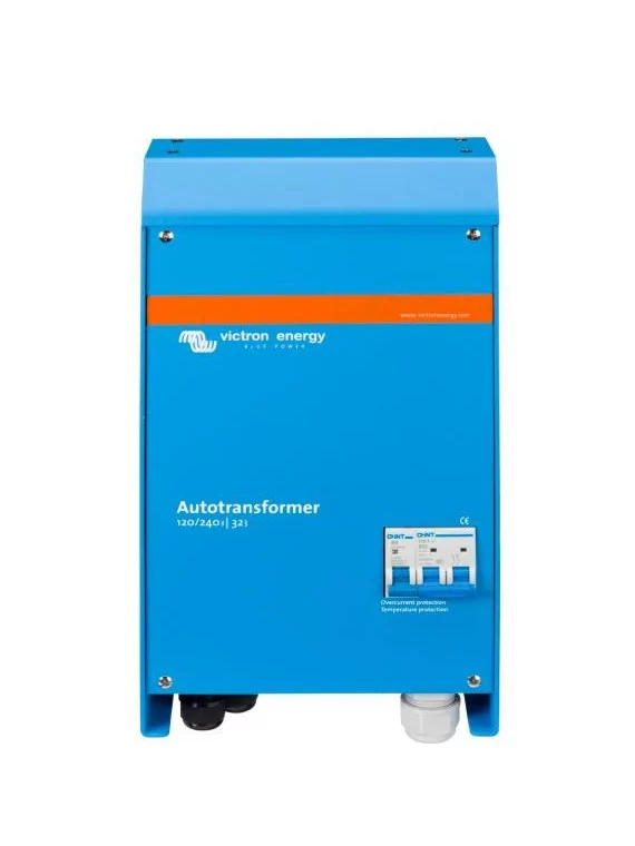
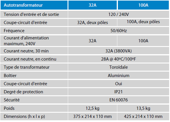
Autotransformer 120/240V 32 or 100A Victron
The auto-transformer: voltage rise and fall and split-phase balancing
An auto-transformer can be used to raise or lower voltages, or to balance the split-phase output. While the voltage step-down and step-up functions are fairly straightforward, the split-phase output balancing function may require a little more attention.
The autotransformer: to raise, lower and balance the auxiliary phase.
An autotransformer can be used to step up or down voltages, or to balance the output of the auxiliary phase. While the step-down and step-up functions are fairly straightforward, balancing the output of the auxiliary phase requires more attention.
If we consider, for example, a 30 A, 120/240 V auxiliary phase supply, the supply could be the mains, a generator or two superimposed converters. Some connected loads are 240 V, others are 120 V. For each 120 V phase, the load must not exceed 30 A. The problem is that as soon as 120 V loads are connected, the two phases will show a different current. This is because 120 V loads on two phases will never be balanced. For example, a 120 V 1200 W hair dryer will draw 10 A on one phase. A 120 V washing machine could even draw more than 20 A from one phase. So, between the two phases, the current difference, or current imbalance, will often be 20 A or more. This means that a 30 A supply will not be used to its full potential. By the time one phase draws 30 A, the other may draw no more than 10 A, and increasing the load by 240 V, for example, would result in the phase being overloaded while the other is still in reserve capacity.
Theoretically, the total power that can be drawn from a 30 A 120/240 V supply is 30 x 240 = 7.2 kVA. In the event of a 20 A imbalance, the maximum that can be drawn is 30 x 120 + 10 x120 = 4.8 kVA, or 67% of the theoretical maximum.
The solution to this is the autotransformer. By leaving the neutral of the auxiliary phase supply unused, and connecting an autotransformer to create a new neutral, as shown in diagram 1, any load imbalance is absorbed by the autotransformer. In the case of a 30 A supply, the load can be increased to 7.2 kVA, and a load imbalance will be created, with one phase supplying 40 A, and the other 20 A. The 20 A difference will pass through the neutral and the autotransformer windings. The current flowing through the 120 V wires of the auxiliary phase supply will be 30 A.
Temperature protection
In the event of overheating, the autotransformer is disconnected from the power supply. Restart is manual.
Ground relay supplied when using a Multi or Quattro converter/charger.
In inverter mode, the neutral output of the inverter/charger must be connected to ground to ensure correct operation of the ground fault circuit interrupter (GFCI). In case of auxiliary phase supply, the neutral must be grounded. For this purpose, an earth relay is mounted on the autotransformer casing. The relay is controlled by the 230/240 V Multi or Quattro. (The internal ground relay of the 230/240 V Multi or Quattro must be switched off).
An alternative to superimposed converters.
The alternative to superimposing two 120 V converters to provide 120/240 V auxiliary phase power is a 240 V converter with an additional autotransformer.
Two 120 V 3 kVA converters will supply up to 25 A to each 120 V phase. If the load on one phase is less than 25 A, the maximum load on the other phase remains limited to 25 A.
A 240 V 5 kVA converter with a 32 A autotransformer will deliver a balanced load of up to 21 A to each 120 V phase. Having less load on one phase, however, will give more power available to the other phase, with a maximum unbalance of 32 A. Consequently, the load on one phase can rise to 38.5 A if the load on the other phase is no more than 3.5 A. (Maximum unbalance: 38.5 - 3.5 = 35 A). If a load imbalance is expected, then a converter rated below 240 V with an autotransformer will be preferable to a stacked converter solution.


